

Updated: 07 of August 2023
What we are going to learn
- How to build a robot in a matter of minutes
- How to see the robot in RViz
- How to move the parts of the robot using Joint State Publisher
List of resources used in this post
- Use the rosject: https://app.theconstructsim.com/l/5a5b6f9f/
- The Construct: https://app.theconstructsim.com/
- My Robot Manipulator repository: https://bitbucket.org/theconstructcore/my-robotic-manipulator
- ROS Courses:
- URDF for Robot modeling: https://app.theconstructsim.com/Course/13
- ROS2 Courses:
- URDF for Robot Modeling in ROS2 : https://app.theconstructsim.com/courses/83
- ROS2 Basics in 5 Days Humble (Python): https://app.theconstructsim.com/Course/132
- ROS2 Basics in 5 Days Humble (C++): https://app.theconstructsim.com/Course/133
Overview
From the URDF model, we’re going to define the first two links and visualize them in RViz. Up to the end of the video, we’ll have a basic model, a launch file to visualize it and a RViz configuration file for this specific project.
ROS Inside!

ROS Inside
Before anything else, if you want to use the logo above on your own robot or computer, feel free to download it and attach it to your robot. It is really free. Find it in the link below:
Opening the rosject
In order to follow this tutorial, we need to have ROS installed in our system, and ideally a ROS Workspace (it can be named simulation_ws). To make your life easier, we have already prepared a rosject with a simulation for that: https://app.theconstructsim.com/l/5a5b6f9f/.
You can download the rosject on your own computer if you want to work locally, but just by copying the rosject (clicking the link), you will have a setup already prepared for you.
After the rosject has been successfully copied to your own area, you should see a Run button. Just click that button to launch the rosject (below you have a rosject example).
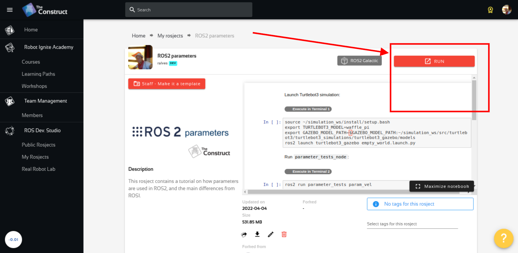
My Robotic Manipulator #1: Basic URDF & RViz – Run rosject (example of the RUN button)
After pressing the Run button, you should have the rosject loaded. Now, let’s head to the next section to get some real practice.
Compiling the workspace
As you may already know, instead of using a real robot, we are going to use a simulation. In order to see that simulated robot, we need to have our workspace compiled, and for that, we need a terminal.
Let’s open a terminal by clicking the Open a new terminal button.
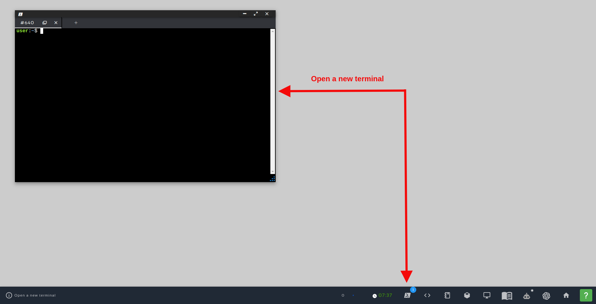
Open a new Terminal
Once inside the first terminal, let’s run the commands below, to compile the workspace
cd ~/simulation_ws/
catkin_make
source devel/setup.bash
How the mrm_description package was created
cd ~/simulation_ws/src
catkin_create_pkg mrm_description urdf
cd mrm_description/
mkdir urdf
cd urdf/
touch mrm.xacro
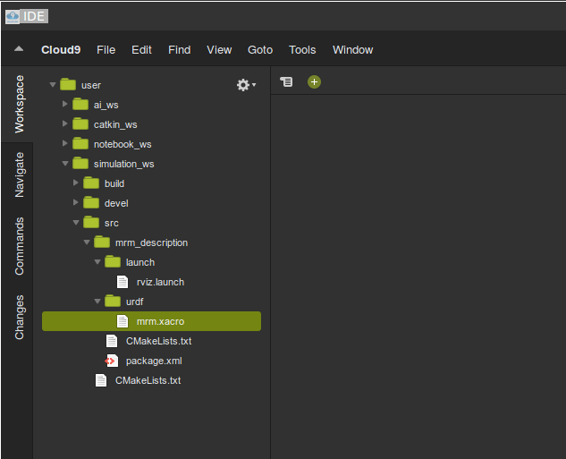
cd ~/simulation_ws/src/mrm_description/
mkdir launch

touch rviz.xacro
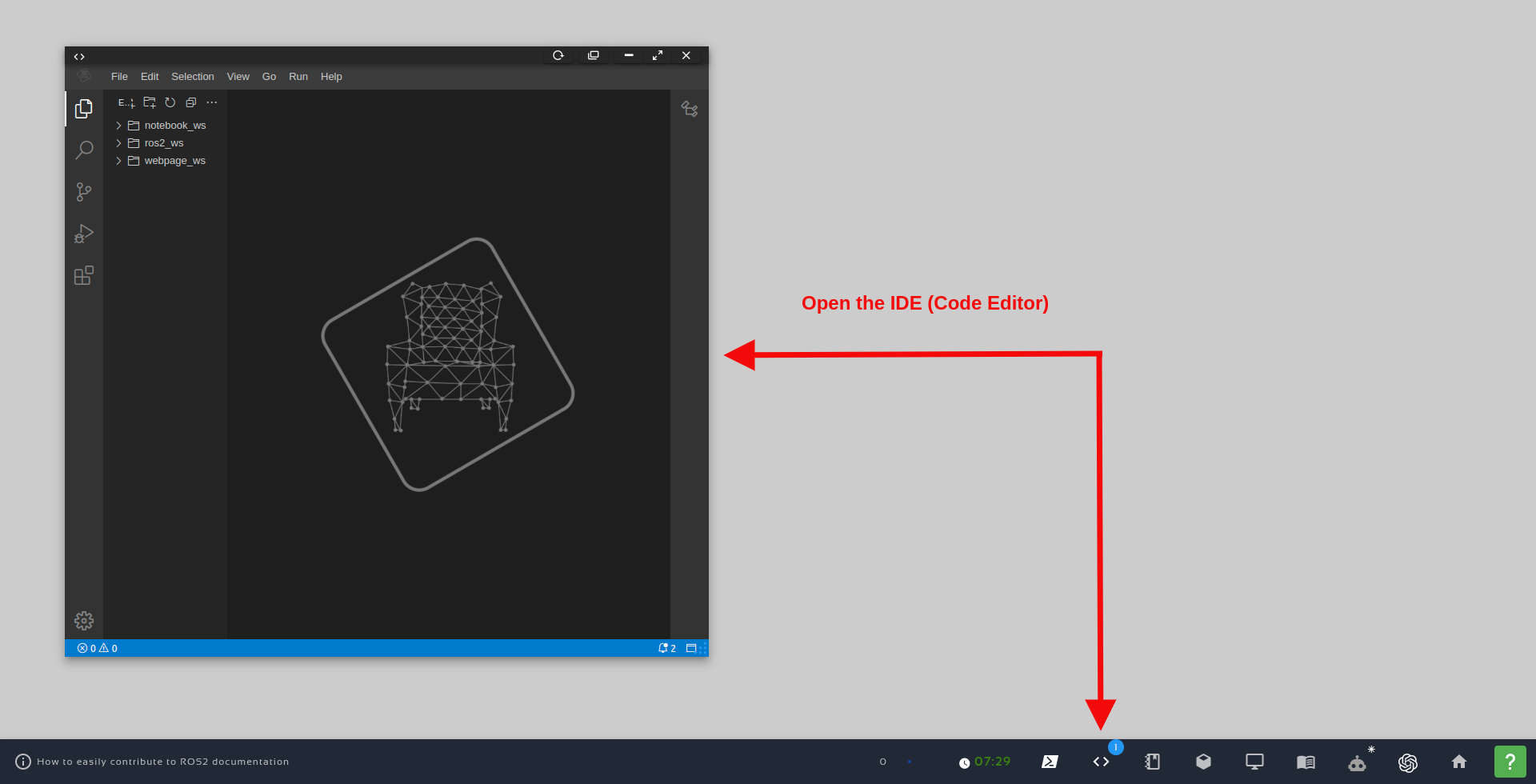
Open the IDE – Code Editor
After opening the IDE, you can browse through folders by double-clicking them. In case you want to create a new folder, right click on the parent folder and choose the option New Folder and type in the name you want to give to the folder.
The mrm.xacro file (My Robot Manipulator xacro file)
If we check the content of the mrm.xacro file, be it using the Code Editor or using the terminal (cat ~/simulation_ws/src/mrm_description/urdf/mrm.xacro), we will find the following:
<?xml version="1.0" ?>

<robot name="mrm" xmlns:xacro="http://www.ros.org/wiki/xacro">
    <link name="base_link">
        <visual>
          <origin rpy="0 0 0" xyz="0 0 0" />
          <geometry>
            <box size="1 1 1" />
          </geometry>
        </visual>
    </link>

    <joint name="base_link__link_01" type="revolute">
        <axis xyz="0 0 1"/>
        <limit effort="1000.0" lower="-3.14" upper="3.14" velocity="0.5"/>
        <origin rpy="0 0 0" xyz="0 0 0.5"/>
        <parent link="base_link"/>
        <child link="link_01"/>
      </joint>

    <link name="link_01">
        <visual>
          <origin rpy="0 0 0" xyz="0 0 0.2" />
          <geometry>
            <cylinder radius="0.35" length="0.4" />
          </geometry>
        </visual>
    </link>

</robot>
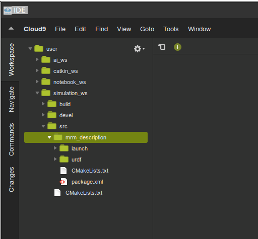
In the IDE (Code Editor), you can find it under the urdf folder:
xacro file contains the description of our manipulator.<?xml version="1.0" ?>
<robot name="mrm" xmlns:xacro="http://www.ros.org/wiki/xacro">
  ...
</robot>
<link name="base_link">
  <visual>
    <origin rpy="0 0 0" xyz="0 0 0" />
    <geometry>
      <box size="1 1 1" />
    </geometry>
  </visual>
</link>
<joint name="base_link__link_01" type="revolute">
  <axis xyz="0 0 1"/>
  <limit effort="1000.0" lower="-3.14" upper="3.14" velocity="0.5"/>
  <origin rpy="0 0 0" xyz="0 0 0.5"/>
  <parent link="base_link"/>
  <child link="link_01"/>
</joint>
<link name="link_01">
  <visual>
  <origin rpy="0 0 0" xyz="0 0 0.2" />
  <geometry>
    <cylinder radius="0.35" length="0.4" />
  </geometry>
  </visual>
</link>
xacro file is a description of our robot in xml language. The robot is composed of various links and joints. In the above xacro we have two links base_link and link1. The base_link is fixed to the ground. It is connected to the link1 with a revolute joint. The joint allows the link1 to rotate about z-axis. We are defining the visual properties in this file.geometry property controls the appearance and origin property controls the positioning of the elements.joint element has an axis property which defines the degree of freedom of the links connected with joint. In addition to the axis property, the joint element has limit property to control the range of motion, parent and child property to control the relative motion (the child link moves with respect to the parent link).The rviz.launch file
cat ~/simulation_ws/src/mrm_description/launch/rviz.launch
<launch>
  <param name="robot_description" command="$(find xacro)/xacro --inorder '$(find mrm_description)/urdf/mrm.xacro'"/>

  <!-- Combine joint values -->
  <node name="robot_state_publisher" pkg="robot_state_publisher" type="robot_state_publisher"/>

  <!-- Show in Rviz   -->
  <node name="rviz" pkg="rviz" type="rviz" args="-d $(find mrm_description)/launch/config.rviz" />

  <!-- send joint values -->
  <node name="joint_state_publisher_gui" pkg="joint_state_publisher_gui" type="joint_state_publisher_gui">
    <param name="use_gui" value="true"/>
  </node>

</launch>
<node name="robot_state_publisher" pkg="robot_state_publisher" type="robot_state_publisher"/>
<!-- send joint values -->
<node name="joint_state_publisher_gui" pkg="joint_state_publisher_gui" type="joint_state_publisher_gui">
    <param name="use_gui" value="True"/>
</node>
Compiling the workspace
Now that we have everything in place, we need to compile our workspace. For that, we use the following commands:
cd ~/simulation_ws/
catkin_make
...
-- catkin 0.8.10
-- BUILD_SHARED_LIBS is on
-- BUILD_SHARED_LIBS is on
-- ~~~~~~~~~~~~~~~~~~~~~~~~~~~~~~~~~~~~~~~~~~~~~~~~~
-- ~~  traversing 1 packages in topological order:
-- ~~  - mrm_description
-- ~~~~~~~~~~~~~~~~~~~~~~~~~~~~~~~~~~~~~~~~~~~~~~~~~
-- +++ processing catkin package: 'mrm_description'
-- ==> add_subdirectory(mrm_description)
-- Configuring done
-- Generating done
-- Build files have been written to: /home/user/simulation_ws/build
####
#### Running command: "make -j8 -l8" in "/home/user/simulation_ws/build"
####
Lauching RViz to see our robot model
In the previous sections we already learned how to open a terminal.
Now, in order to launch RViz, let’s run the following commands in the first terminal:
source ~/simulation_ws/devel/setup.bash


roslaunch mrm_description rviz.launch
The GUI tool is like a remote desktop, when it starts you can see there are two tabs at the bottom. One is the RViz tool, and the other is the joint_state_publisher GUI as shown below:
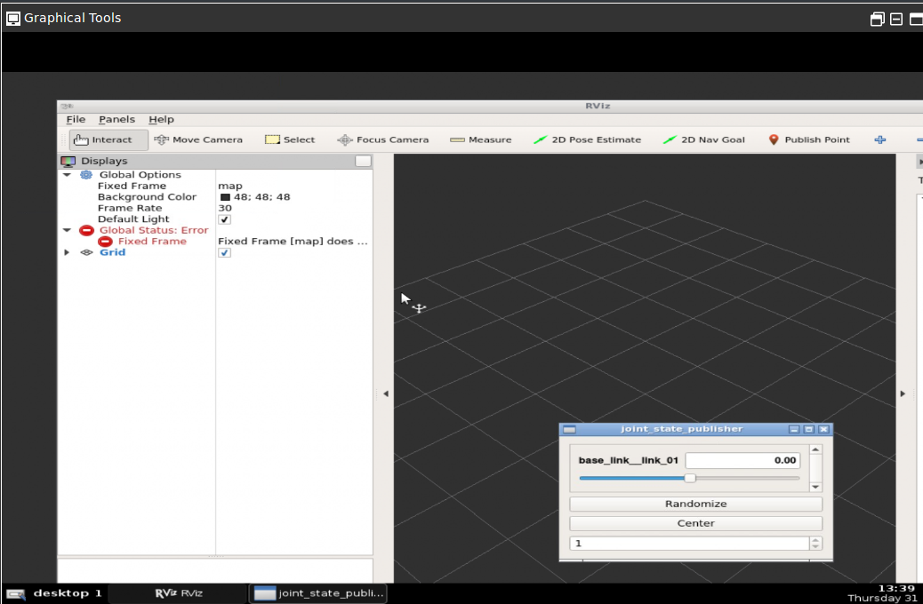
In the RViz window, we should have everything in place. We shouldn’t have the red errors like in the image above, because in the rosject we already provided the config.rviz in the launch file, if you remember well.
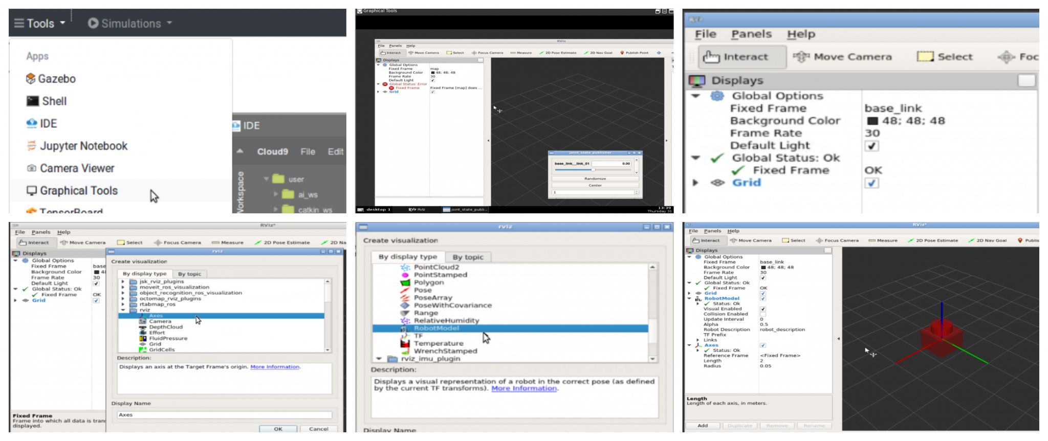
What we did for creating that config.rviz file was the following, in RViz:
- Changed Fixed Frame to
base_link - Added an Axis element
- Added a RobotModel element
The images below show the operations described above:
Congratulations. Now you know how to create a basic robot with two links and a joint using Xacro files.
We hope this post was really helpful to you. If you want a live version of this post with more details, please check the video in the next section. Although the video was recorded in a previous version of The Construct platform, it still adds a lot of value:
Youtube video
So this is the post for today. Remember that we have the live version of this post on YouTube. If you liked the content, please consider subscribing to our youtube channel. We are publishing new content ~every day.
Keep pushing your ROS Learning.
Related Courses & Training
If you want to learn more about ROS and ROS2, we recommend the following courses:
- ROS Courses:
- URDF for Robot modeling (ROS 1): https://app.theconstructsim.com/Course/13
- ROS2 Courses:
- URDF for Robot Modeling in ROS2 : https://app.theconstructsim.com/courses/83
-
- ROS2 Basics in 5 Days Humble (Python): https://app.theconstructsim.com/Course/132
- ROS2 Basics in 5 Days Humble (C++): https://app.theconstructsim.com/Course/133
- Open-RMF / Fleet Management Training: https://www.theconstruct.ai/robot-fleet-management-ros2-open-rmf-training/


when I typed in $ catkin_make for step 3, I got message like this:
Traceback (most recent call last):
File “/opt/ros/melodic/bin/catkin_make”, line 12, in
from catkin.init_workspace import init_workspace
ImportError: No module named catkin.init_workspace
how to solve it? Thank you.
Hi Nick,
You probably don’t have the $ROS_PACKAGE_PATH well configured.
Make sure you have sourced your ROS installation path (e.g: source /opt/ros/melodic/setup.bash) and then try to re-compile it again
In order to run this tutorial 2021 in Noetic you need to change the following in the rviz.launch file:
1.
original:
change:
2.
original:
change:
1.
2.